2024-07-26 11:56 - Making
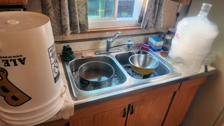
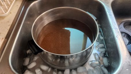
I don't drink a lot, but some. Recently I got it into my head to try home brewing. After a while I picked up some cheap used equipment, and supplies including an easy ingredient kit at a local home brew shop. I've just barely completed the steps for my first brew, here's how it went. Above was the result of brew day: After boiling the malt extract and hops I had the wort, here pictured cooling down in the sink. Beside that are two fermenters: a pail and a jug style. I started with the jug. (Which is capable of a 5 gallon brew, but for my first go I did a one gallon batch.) In the first picture you can see it full of foam. That's the no rinse sanitizer. Brewing is all about convincing some yeast to work for you, and just about the most important part of that is keeping out the bacteria that want to ruin things. You don't rinse the sanitizer because if you did, it would introduce more new bacteria!
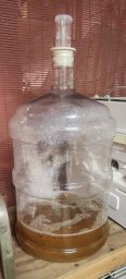
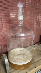
Once the wort was cooled down enough to not kill it, I pitched the yeast in and set up the airlock. The yeast will "fart" out a bunch of CO2, which needs to escape the fermenter (or otherwise the pressure will eventually explode). The airlock lets the CO2 out without letting anything else (bacteria!) in. Above you can see day one: some of the sanitizer foam is sitting on top of the wort. By the next day plenty of yeast has grown, and has bubbled some sanitizer out of the airlock. For this first go I was trying to follow the kit's instructions as closely as possible, but here's where it went wrong.
It takes a fair deal of time for the yeast to do their work. I had read up ahead of time, and had it in my head that about one week was the right time for this fermentation step to take. The instructions want me to do a secondary fermentation (which per my reading is not terribly common), but I did it. However I missed a detail: the instructions wanted primary fermentation to be 4-6 days and (emphasis theirs) before it completes — but it only said that in a note on the side, which I missed. I had been checking more or less daily, and ended up switching to secondary on day 5, but I believe it was too late. The instructions told me to wait "about two weeks" for secondary fermentation, but daily monitoring showed absolutely no activity. So I cut it short after just one week.
So after carefully sanitizing everything involved again, I transferred the beer (I think it is indeed beer now, not just wort) to the bottling pail. (It's got a narrower outlet, which the hose fits on, and more of a siphon inlet. The fermenter pail simply has a hole, a bit above the bottom, to facilitate transferring the liquid but not the sediment.) And bottled! The

Here's bottling day, complete. I planned to use a couple capped bottles (for longer term storage/comparison) but focused on my flip-tops. But did the math in my head wrong so I had extra bottles, which is better than too few! One of the more subtle steps of bottling day is to actually add a bit of sugar to the beer. The remaining yeast processes this, in the bottles, to add carbonation. So although I'm "done", the instructions say I should wait two weeks (and up to an extra week!) for this bottle conditioning to complete. Almost there!
My one gallon kit filled about ten and a half bottles. Or, a bit less than two six packs. This does not excite me, but a five gallon brew can be done easily for the price of two or three (quality) six packs, and if I shop carefully, for less than a (cheap) 15 or 18 pack. Assuming my first results here are good, I'll be aiming in that direction. Though, I'm still figuring out how/whether I can handle boiling five gallons all at once. (I think you can get away with boiling less, then topping up with more water after.) Also: five gallons is a lot of beer to drink!
2024-04-22 16:51 - Making
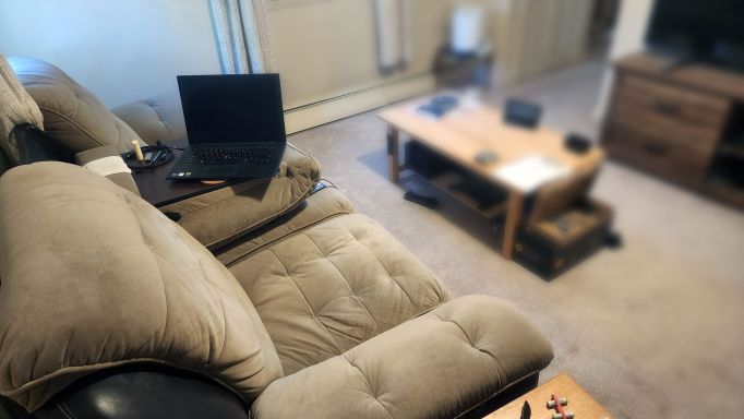
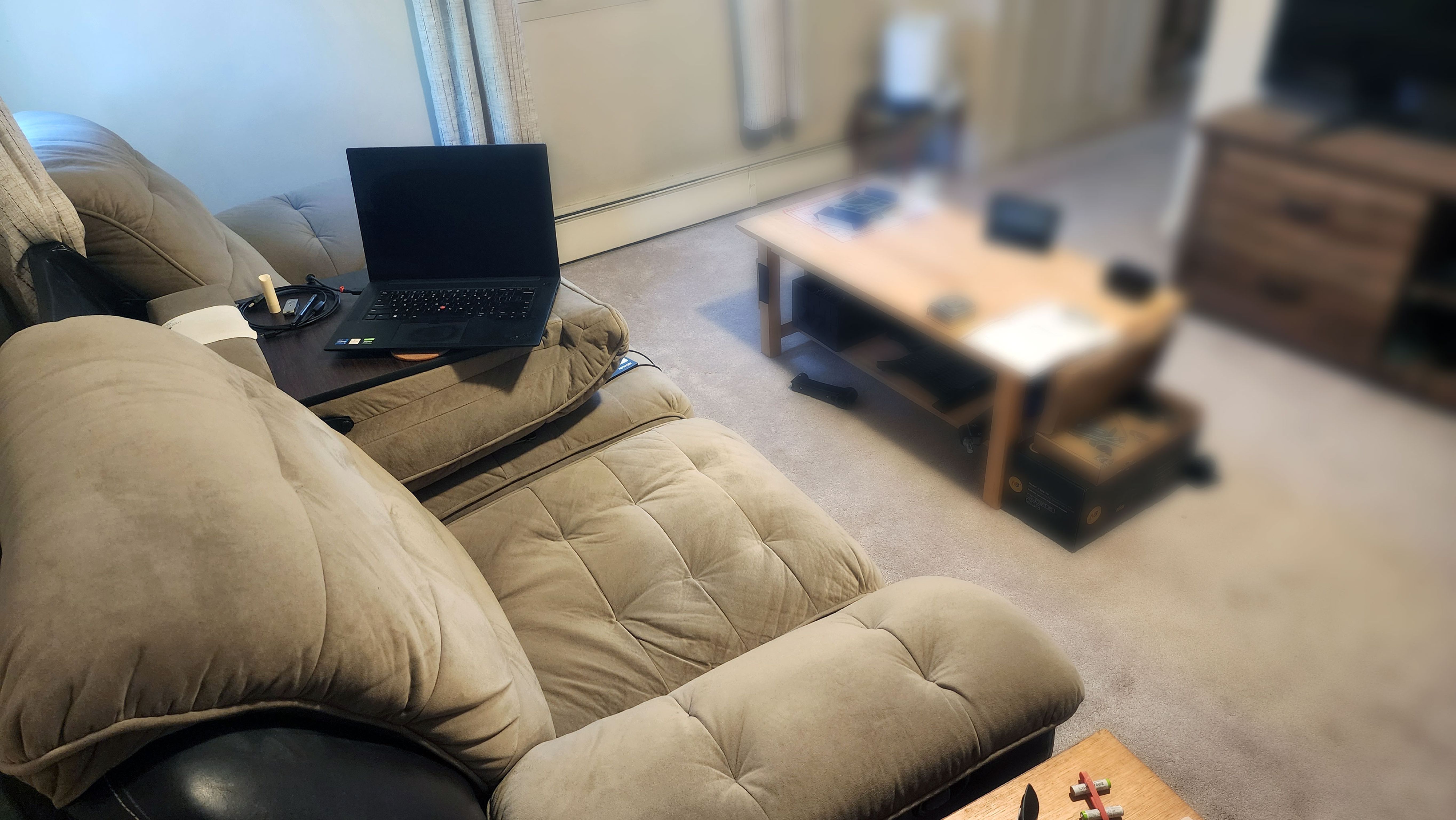
For a bit over a year, I've had my laptop sitting on this fold out table built into the middle seat of my sofa. It's okay, but it's not great. It's a bit too far to the side and too far back to make usage really comfortable and practical. For a while I've thought about mounting an arm that would hold the laptop in a more adjustable and flexible place. I finally did something about it, with the commercial arm arriving just yesterday. With it in hand I saw exactly how it worked and what size it is, so this morning I started drafting plans for how to mount it. Something made of wood, attached to and/or wedged under the structure of the sofa. I simplified through a few revisions.

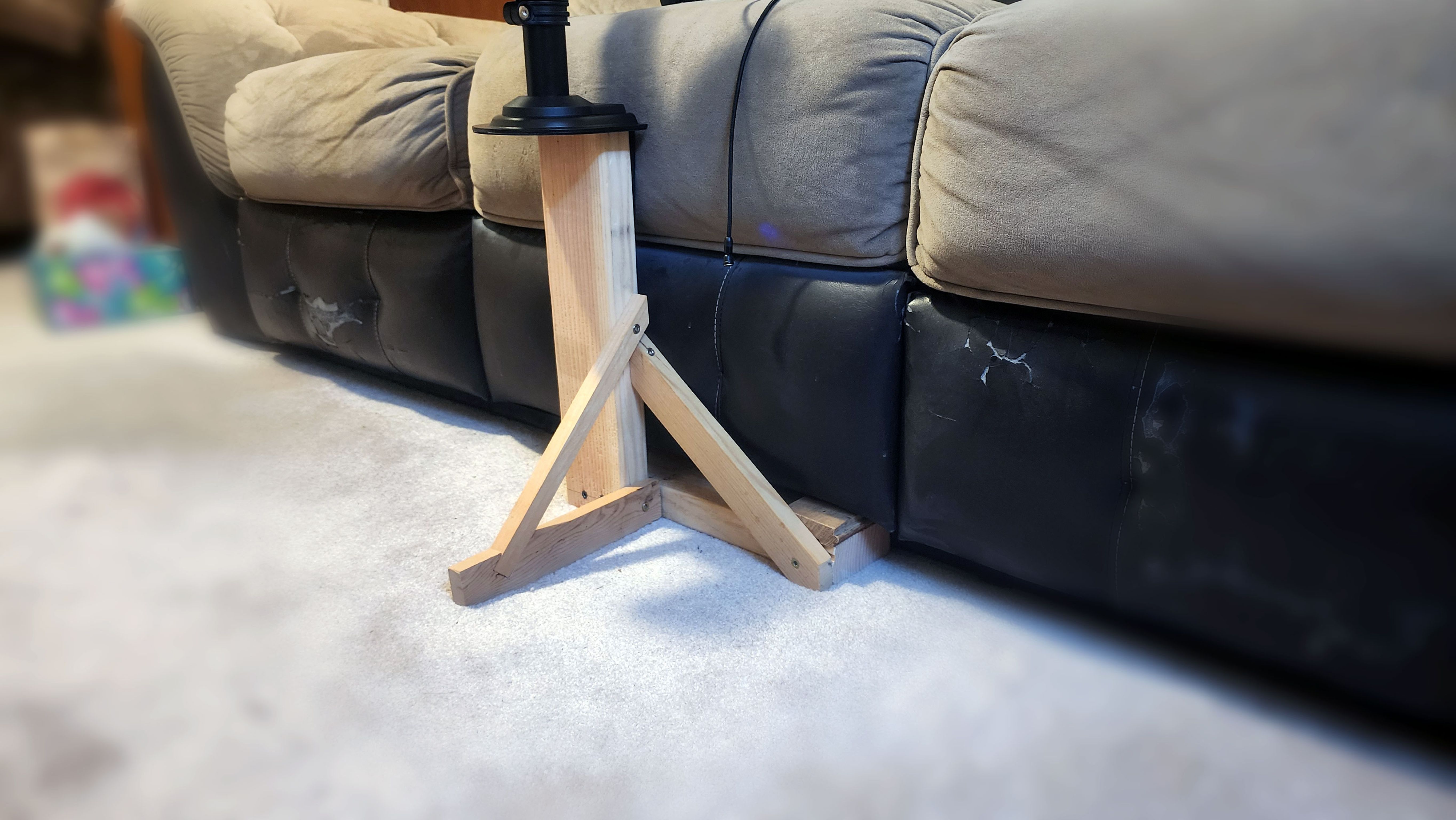
This is what I came up with. It's an L shape, with the arm mounted to the top of the vertical leg, and the horizontal leg fitting under the front of the sofa. The horizontal leg prevents side-to-side tipping by pressing against either the floor or the sofa. A triangular brace makes that reliably strong, and a second prevents the vertical leg from tipping away from the sofa. The L part was designed somewhat carefully, while the rest was just made to fit. Everything was material already available in the basement. A C clamp is hidden by the triangular brace, holding the horizontal leg of the L to the sofa's metal frame.

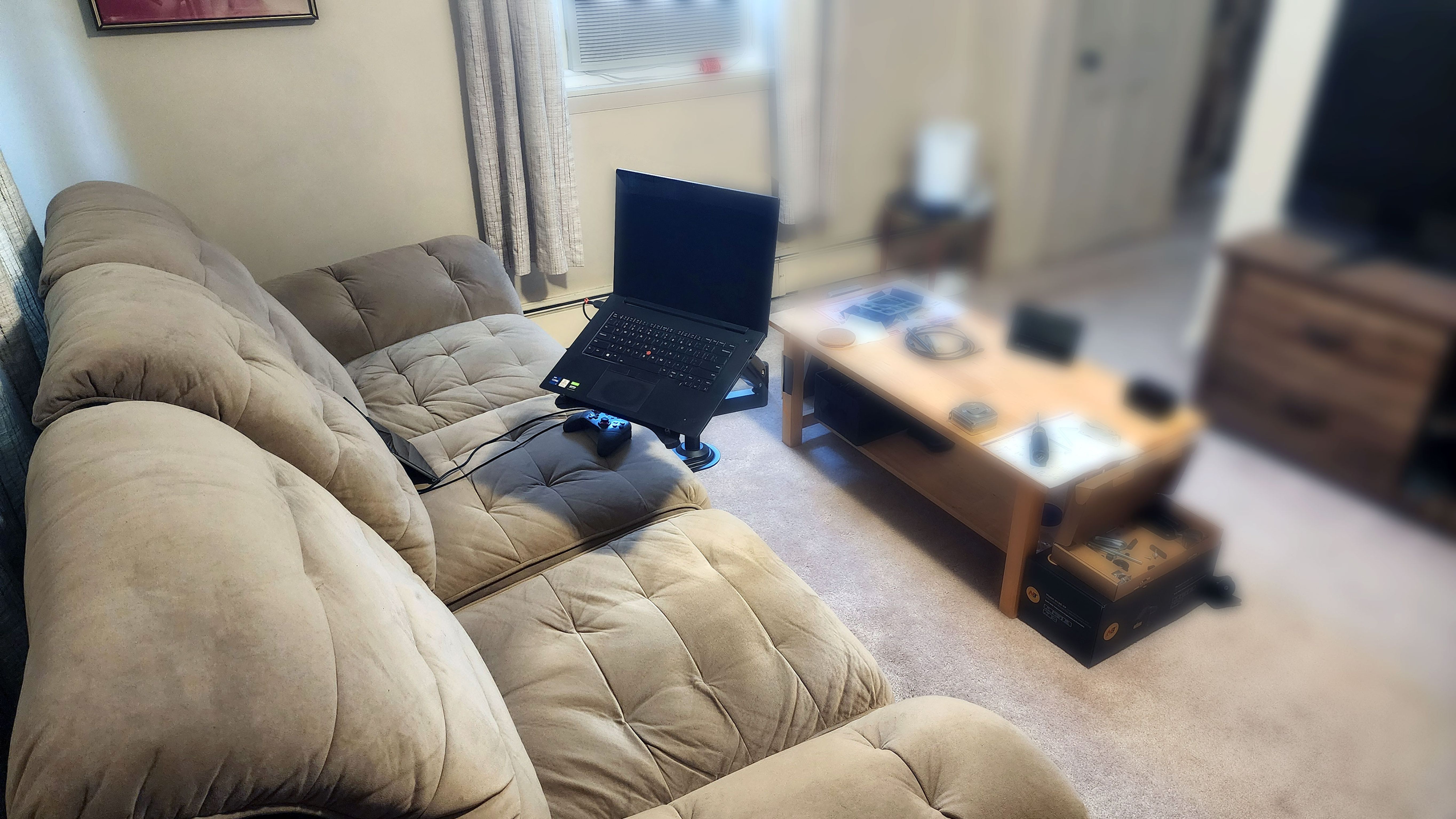
And here it is. I can pull the laptop almost down into my lap and push it further away from me, with very little effort. I've got pretty much exactly what I was hoping for.
2024-01-24 16:26 - General
The drainage in the backyard here is not great. At the corner of the driveway, there's a tiny drainage ditch which should help. But that corner of the drive way is not (is no longer?) the low spot. So when there's enough rain, a significant portion of the driveway ends up forming a large puddle. Last time I visited Mom, I brought back a 2-stroke edge trimmer, with the idea that it's the perfect thing to dig a tiny supplemental "ditch" along that edge of the driveway, to help get the water away. (Into the existing drainage ditch, from the too-low parts of the driveway. As-is the grass and dirt comes right up to the concrete, holding the water in pretty effectively.)
Today there was just enough of a break between the snow (now melting) and rain (forecast to start this morning, but not here yet) that I thought: now's the time! I gave it a shot and couldn't start it. (I'd guess it's been over a decade since it has run.) I checked the spark plug: very dirty, but I could see at least a faint spark. So I dribbled some gas straight in the cylinder, and then I did get it to start, and run but for only a second or so. So what's the problem? Fuel delivery!
Took off the tiny carburetor to investigate. Got surprised by the air intake path: there's only one option from the carburetor side, but it comes through a strange path. I can just see a foam air filter peeking out in one spot, but not where air gets into the other side of it. But then I wondered: wait, where does the fuel come in? Found the intake on the carburetor, which didn't have a fuel hose attached. Found that and ... quickly learned that it's hardened to unusability. And in fact, already broken in half. This is probably the primary problem.
It's so bad that a piece of it crumbled in my hand, just holding it, while trying to figure out the size. With the bit that was left, I managed to figure out that a 1/16″ fit a little loosely but a 5/64″ fit snugly. It snakes a complex path from the tank to the carburetor, so in addition to needing the right size to connect on either end, I'll need it small enough to fit through all those passages, too!
2024-01-11 23:24 - Gaming
I have a significant collection of video game consoles. Wherever possible and practical, I prefer to "mod" them. Mod is short for modify, and generally means lifting the restrictions that they come with — mostly for copy protection. These mods have many benefits but a significant one is being able to run games without relying on the optical drive the whole time. In these ten or twenty year old devices, the moving optical drives often fail.
Back in 2015 I tried to mod the XBox 360 I had at the time. Long story short, I failed to remove the "x-clamp" (which holds the heat sink down to the APU) and damaged the logic board in the process. (I still have all those parts, maybe I should try some trace repair again.) More recently I accepted an XBox (OG) and XBox 360 that was being given away. Then even more recently I heard about the "RGH3" mod. The 360 has pretty good protection built in. For a long time, besides some simple piracy-only based modifications "RGH" (reset glitch hack) was the only way to mod a 360 for full control. The idea is based around sending a very brief reset signal to the CPU at just the right time, so that as it is performing verification checks very early in the booting process, the check (and only the check) can be corrupted. Then the console otherwise boots as normal, but has not verified its firmware. This used to take a special extra "mod chip" and quite a bit of very careful wiring. The third version, RGH3, amazingly uses the console itself to send this reset glitch signal. That makes it a comparatively very simple modification: just two wires. (Two permanently, a few more temporarily.)
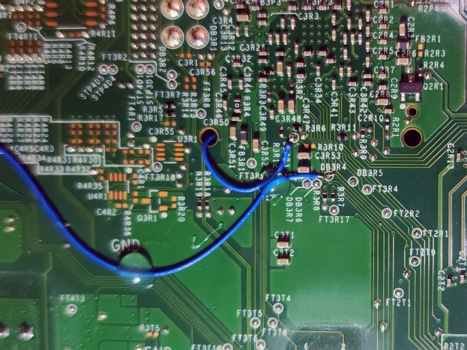
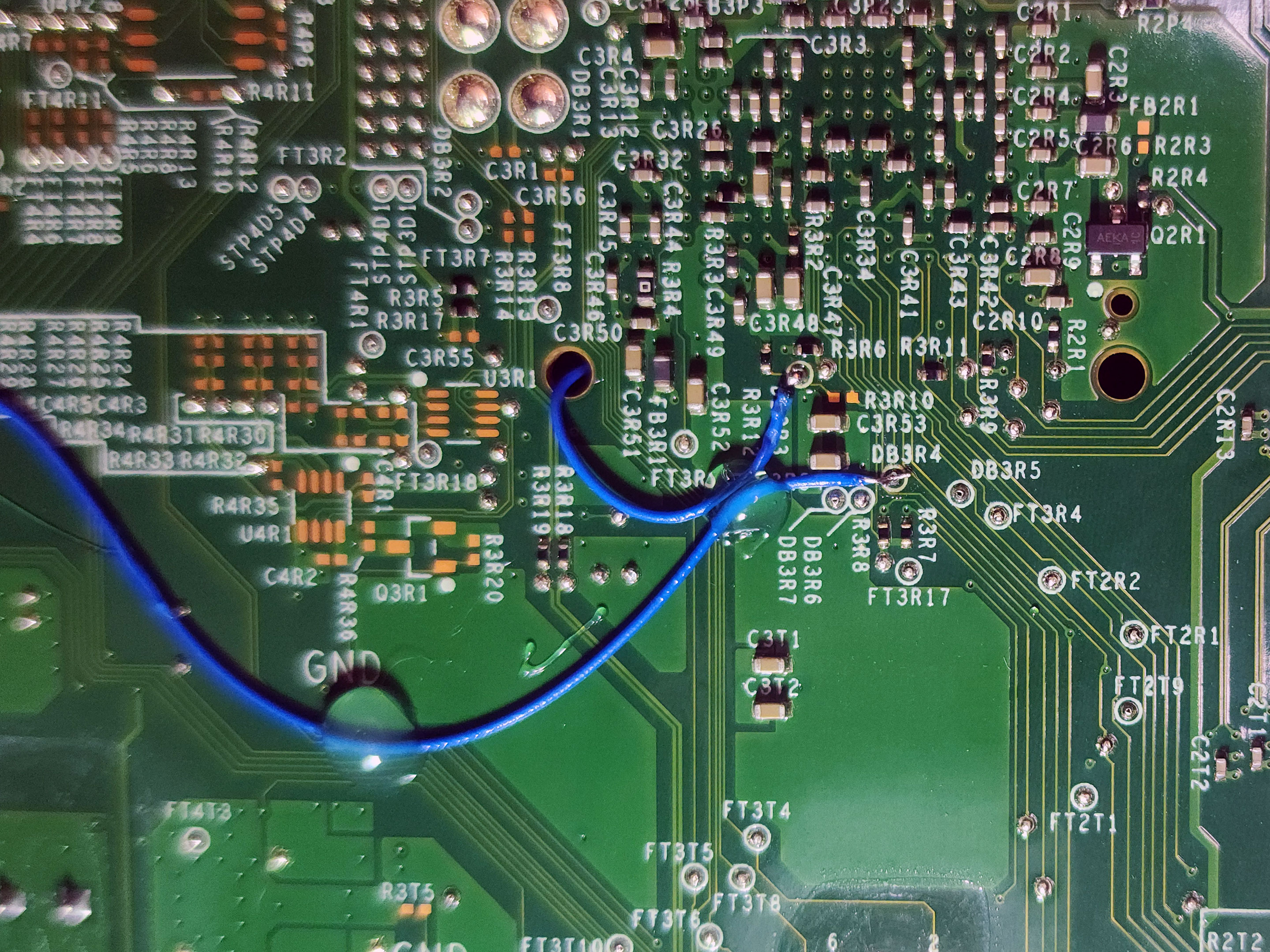
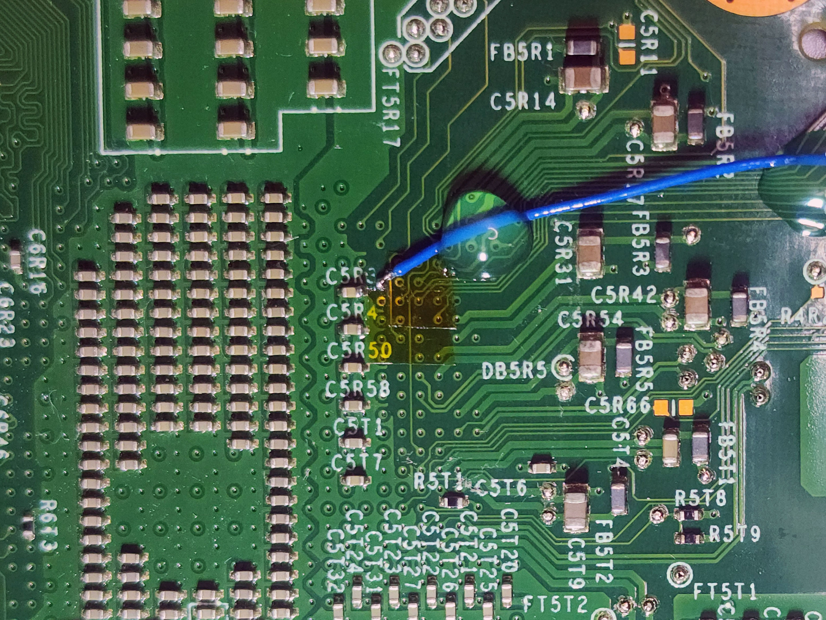
Last month, I opened up the 360. I confirmed that it's a newish (relatively speaking) "Corona" variant. Because it's new, it's designed to prevent RGH style attacks. Because the modding community(/related business(es)) is clever (and a bit lucky) there is a "POST fix adapter" to restore access to the otherwise removed signal trace. It just so happens that this is one of the outermost "pins" of the APU, so a carefully positioned piece of wire can touch it. And the adapter is designed to hold a little pin in just the right spot. That's one end of one of the two wires needed. The picture above is the other end of the two wires. With POST dealt with, these are the two "easy" remaining connections. They're tiny, but they're exposed and directly available. (It's not unusual for all sorts of important signal traces to have test points in commercial products, intended for use during design and manufacture.) I'd estimate that the white circles drawn around these two points, where my added blue wires terminate, to be about one millimeter across. Possibly one and a half. Those blue wires are 30 gauge "wire wrapping" wires. The wire itself is 0.255 millimeter in diameter. The higher of those two solder points I did rather well on. The lower/rightmost one isn't as great. The exposed wire is too long and the solder has barely attached it. But attached it is! I got away with it.

Here's the remaining wire end. It's attached to a via, which starts off covered in solder mask. The point of this mask is to prevent solder from going here. This must be scraped off, without damaging the tiny and fragile exposed copper part of the via. I did so with a fiberglass "scratch pen". I slightly exposed an adjacent via and track, so those were covered with some polyimide tape before proceeding. For this one, the via-as-solder-point is hardly wider than that quarter-millimeter wire. This one took a few tries, and I ended up leaving a little extra solder on the capacitor. Once this tiny joint was complete however, I didn't want to mess with it.
I added some tiny dabs of hot glue to keep the wires in place, to avoid breaking these fragile joints through mechanical fatigue. I also added an in-line resistor on one of the lines as suggested by the guide I was following. The following steps were mostly software based. When first flashing Xell (xenon linux loader — xenon is the code name for the first XBox 360 variant) the first time it didn't take. I turned the 360 on and Xell should have launched, but the standard retail dashboard did, instead. After sleeping on it I wrote Xell a second time and somehow this time it worked. This is just the first step however, unlocking the next step: the XeBuild which actually modifies the console's behavior. (It requires knowing the per-device encryption key, which Xell somehow is able to read.) This also did not boot after flashing it, this time Xell remained. I tried writing a second time, and this did not work. But Xell also supports writing this sort of update, so I tried a third time using it (instead of the PicoFlasher I used to get this far) and it worked. From there I just had to install some custom software and I was in full control, huzzah!
2024-01-03 15:37 - Opinion
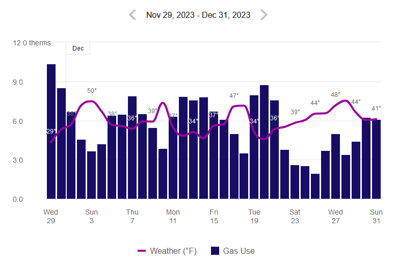
Not only is it common for thermostats to offer features to set different target temperatures at different times of day, it's commonly advised that if you (during heating season) "lower your thermostat one degree, you'll save" about 1 percent for each degree of thermostat adjustment per 8 hours or [net] 3% on your heating bill or between 1 and 3 percent of your heating bill or by regularly turning down the temperature by 10 to 15 degrees before leaving the house for an eight-hour span, you can save between 5% and 15% a year on your heating bill. Though, most of the sources I could (easily) find all cite the same Department of Energy numbers, which repeats "You can easily save energy in the winter by ... setting it lower while you're asleep or away from home" and "During winter, the lower the interior temperature, the slower the heat loss".
That last point comes closest to convincing me. Yes, it is definitely true that a lower temperature delta directly relates to a slower transfer of energy. But if it's 30° outside and 70° inside, how much can it really matter whether that delta is 40 or 38 degrees? I've doubted this since I was young, living in my parents house and not in control of the thermostat. Then I moved into apartments where I didn't control the heat. But now, I'm living in a detached home and I do control the thermostat.
Because it's programmable, it's easy to set it cooler overnight, for less heating. So I've done that. But does this really save any money? I can only dive deeper into the data I have, for the ~70 year old home I'm in. But that's at least something.

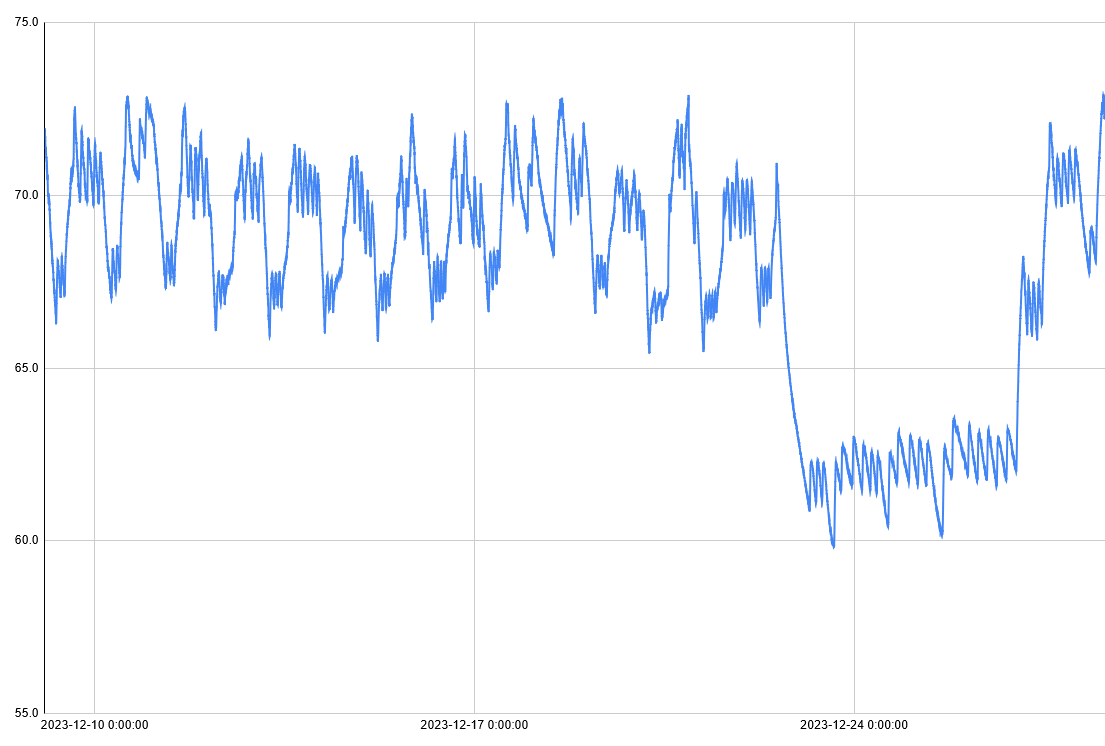
Here's the full data set I'm operating from, covering most of December 2023. Critically this includes nearly a week around Christmas. I was traveling then and set the thermostat extra low. Normally it's set to 71°, I let that drop to 67° "overnight" and all the way to 60° while I was away for a few days. (I think? The graph looks higher. It's set to 60° now...) This is generally visible in the graph above. Though all days vary widely as the weather does, the difference is clear, especially e.g. between the 21st and 22nd.
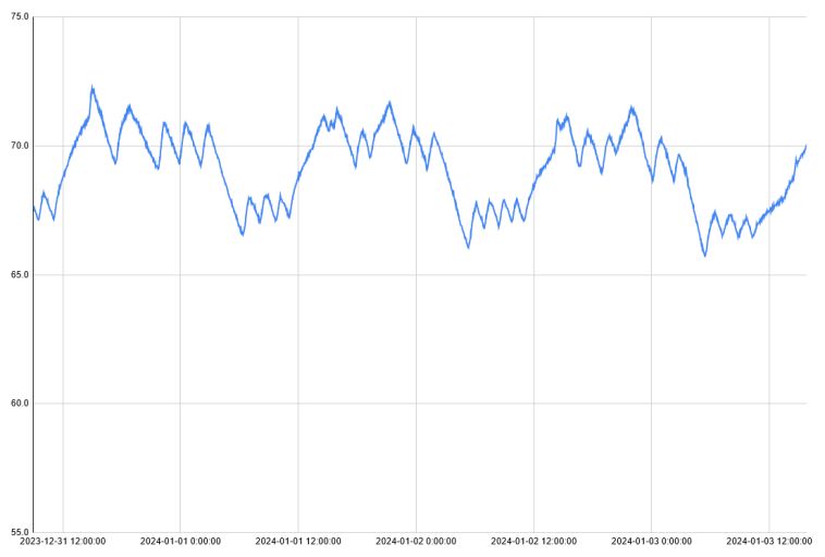
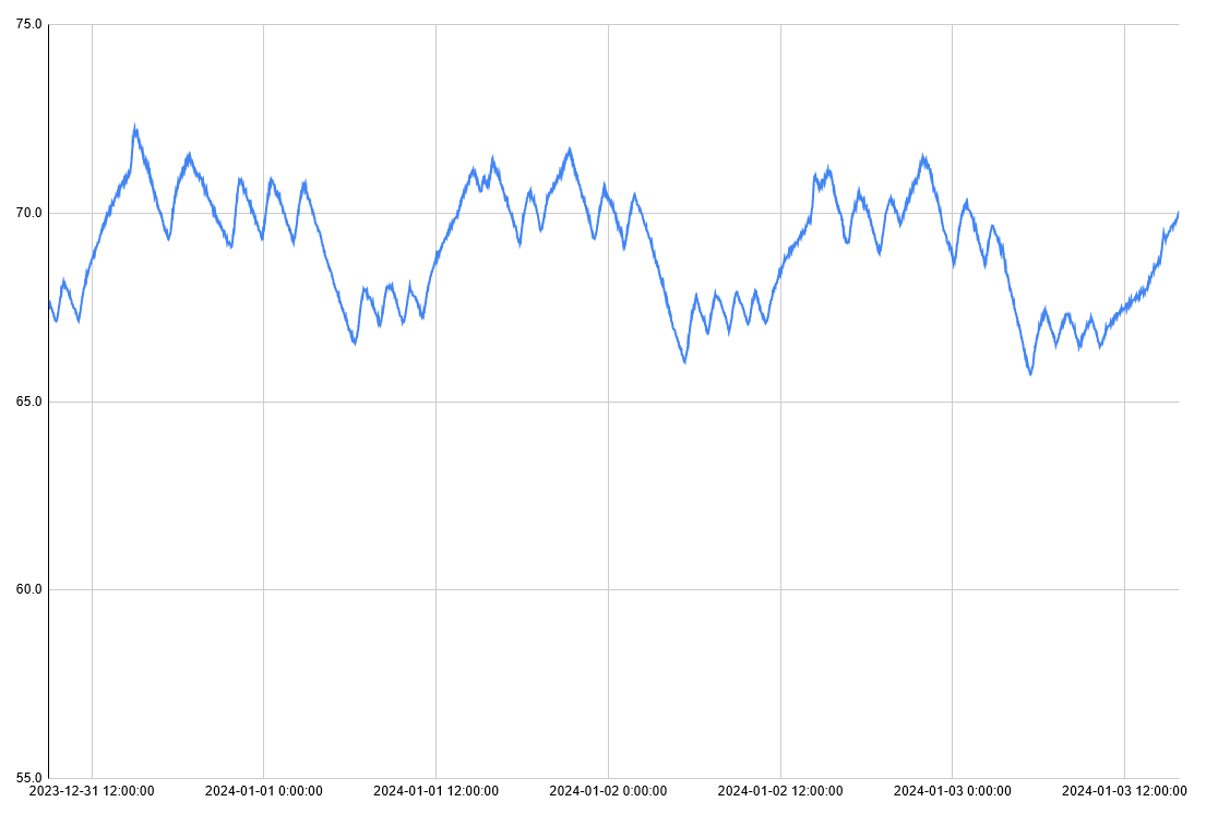
Here's a closer view of just the past couple days, and thus a better view of the topic really in question. Do I save money overall by letting the heater relax overnight? My argument (which I'll soon try to back up with data) is no: The jagged peaks and troughs while the thermostat maintains that slightly lower temperature overnight look very close to those during the day, while it maintains a higher temperature. Then yes there's a large period each evening where there's no heating going on, but a seemingly equal period in the morning as the heater works overtime to raise the temperature back up.
I let the thermostat relax starting at 10PM. (This is hard to see in the graphs because the their time zones are incorrect, whoops.) A normal heat/cool cycle can be roughly two hours, and it might have just completed at 10:00 PM, or just be about to start, or anywhere in between. Temperature has fallen below the night setting (so the furnace starts up) usually by 12:30 to 1:00 AM, where it stays until 6:00 AM when the thermostat resumes its normal daytime setting (this one, always on time because it's always well below that newly active setting). It then takes until 9:30 AM, sometimes a bit more, to satisfy the thermostat that normal daytime temperature has been reached. Very close to the same three and a half hours to fall to, and to rise from, the lower overnight setting.
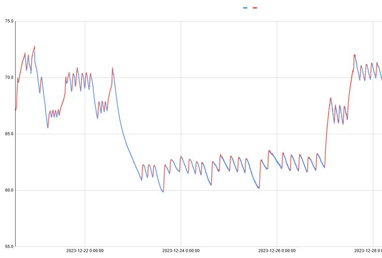
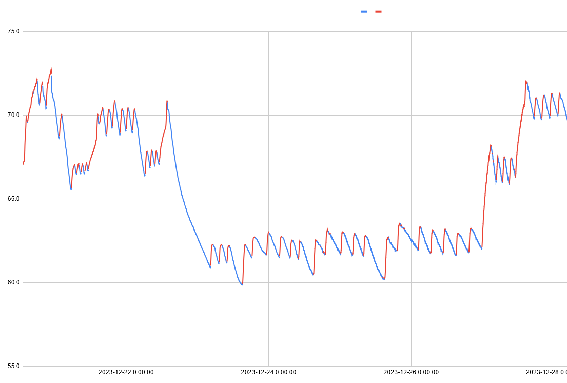
This might be the most interesting graph. I've managed to color-code it red while heating and blue while not. That's visually interesting but hard to use directly. However, I've used the "rising" and "falling" signals that controls the color of this chart as an input for further consideration.
Outside temperature is a confounding factor for such analysis. I've tried to analyze a wide enough time range to average out its effects. Also, I've applied moving averages to try to eliminate measurement noise from the result. That said, first result: there were 13,484 minutes where the temperature was rising and 20,354 where it was falling. Or: the heater was active for 39.85% of the time, perhaps call it 40%. But we'll save those significant figures because the next step is to wonder: how does that proportion vary depending on the set point of the thermostat?
I wrote some code to group these rising and falling temperature periods together, and distinguish them by the current temperature when switching from one to another. (I.e. if we were rising and are now falling, and the temperature is over 70: that's a normal daytime event. And so on.) And here's the results (time is minutes):
| Setting | Time On | Time Off | Percent On |
| Normal | 7,996 | 10,425 | 43.41% |
| Night | 3,931 | 5,201 | 43.05% |
| Holiday | 1,556 | 4,728 | 24.76% |
For the data above I had my little program simply look at whether the temperature was rising or falling, and whether it was closest to the normal, night, or holiday range. Then for each minute, record which bucket we fell into. (I tried other more clever-seeming things, but they made the three hour coast or burn always get recorded completely into the "wrong" bucket, throwing off the numbers. There's really no good way to record those long segments that are partially normal and partially night time.)
First: Clearly setting the thermostat down by 11° has a real effect: I spend 75% more (!) (time with the furnace on, thus) energy to heat this home to 71° as compared to 60°. (In December average temperatures were mostly in the 40s, and those days I was away were right in the typical range.) That's much more of an effect than I expected. I left early on the 22nd and returned by early evening of the 26th. Average outdoor temperatures were roughly 45° for that time. Or, the furnace had to add 15° to get to 60° vs. adding 26° to get to 71° — almost exactly a difference of 75%! It's definitely worth turning the furnace down when leaving for several days straight.
We can confirm this with usage data from the utility:
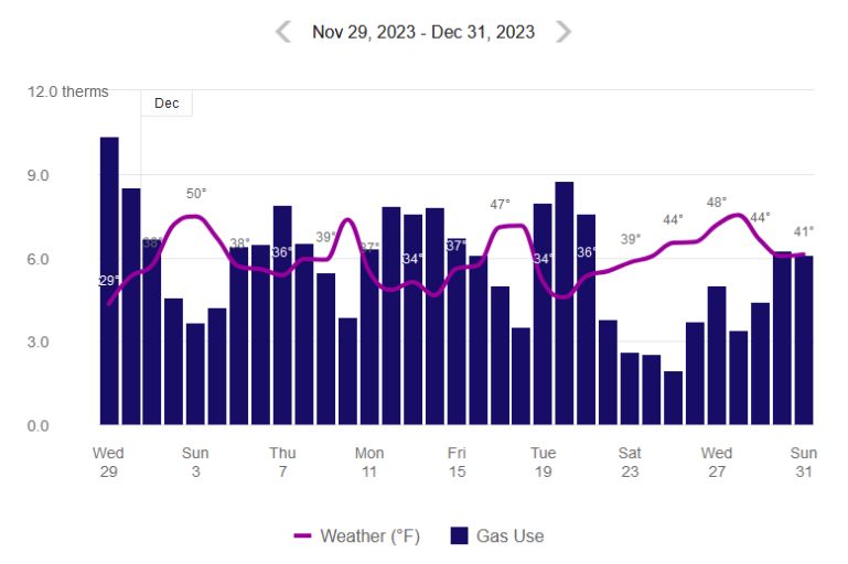
This says weather on the 15th/16th was very close to that on the 23rd/24th. But gas usage was 12.8 vs. 5.1 on those two pairs of days, respectively. An even bigger difference, though of course I wasn't using hot water or anything else while I wasn't here.
But "normal" vs. "night" results are so close as to be indistinguishable from measurement noise. For this house with this furnace, the idea of night time energy savings look just as wrong as I originally thought. I'll wager that with better insulation the inside temperature would fall slower, perhaps the furnace could stay off all night or nearly so. And might even rise faster (i.e. more efficiently) in the morning. But here, it doesn't seem to happen.
How about in theory? Starting from the same 45° we examined before: Raising the indoors up to 71° is a difference of 26°, and my relaxed setting is a difference of 22°. A theoretical difference of 18%, but not borne out by actual observed measurements. But that "average 45°" comparison only made sense when I was inspecting several whole days at the same setting. In reality, the outdoor temperature falls by much more than four degrees overnight, so I'd expect to use the heat more, then. Maybe I'm really saving roughly 20%, but also spending just as much more due to the lower night time outdoor temperature? I'd have to not drop the thermostat overnight for a while and re-run this whole analysis to try to figure that out.
2023-10-05 11:57 - General
My last post was about some scheduled maintenance I did to my car. Slightly ahead of schedule, because I don't know its history from before I bought it. Better to waste a tiny bit of money doing maintenance early than a big amount when something goes wrong thanks to poor maintenance. One of the items on the list was a tire rotation. This should be a pretty easy job.
I got my "childhood" (late teenage of course, if true, but there appears to be a sticker on the box from a few years too late for that) car tool kit from Mom's house last month. It's got a pair of jack stands and a hydraulic jack which are perfect for this. I actually jacked the car up first, forgetting my order of operations. Put it back down and proceeded to loosen the wheel nuts with the wheels on the ground. I had a little trouble at first (we'll get back to this, later), on one of the rear wheels. Front wheels I've gotten all the nuts off "no problem", and re-installed them to torque spec.
Well, actually: I did have some problems with the nuts. I got lucky that I found a breaker bar around Opa's workbench which was long enough to give me enough leverage to budge some of the nuts which the four-way tire iron couldn't. But in ½" drive, I only had 12 point sockets of this size, which probably did not help! But after this point I got everything off that I tried to get off, though I had to put so much force that I shook the whole car.
Why did I have problems? First, an almost-definite contributing factor: auto shops with huge air impact guns over tighten lug nuts, making them extra difficult to remove. But apparently also: Ford's swollen lug nuts is not only a known problem but there's been a lawsuit about it. (Which was dismissed, but still evidence that this isn't a rare issue.) They've got a structural nut, plus a softer (and prettier?) metal layer wrapped around that. The second layer can shift and swell, making it hard to get a socket on and hard to remove the lug nuts. (For more, see the YouTube video Easily remove swollen lug nuts on Fords — that method is just cutting the softer outer layer off! The video clearly shows both the before and after view of this.) I didn't know this when I started. At least one nut, I stripped/rounded it a bit. Since then, I got a bolt extractor kit. This morning, I forced that extractor on the worst bolt.
And I heaved, and I huffed and I puffed, and I could not get it off. I put my impact driver on it. Nothing. So finally I found a pipe to act as a cheater bar. Unfortunately the extractor I could get locally has only a ⅜" drive, so I didn't have a very big wrench attached. (The extractor kit has online reviews, one of which mentions removing a 135-lb-ft spec nut. My lug nuts' spec is 100-lb-ft, so the extractor should handle this! But who knows how overly-tight some shop might have made this in the past?) The wrench bent before the nut came loose. At this point I was worried: I hammered that extractor on the nut (which as I understand is typical use for an extractor). But the nut didn't come off, so how will I get the extractor loose? I certainly don't want to drive around with it on.
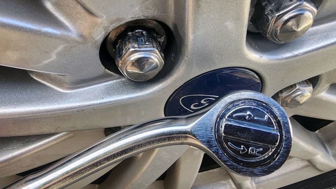
Well, remember how the nut actually has a weak (very probably aluminum) outer layer? What I managed to do was not loosen the nut, but to rip holes in that outer layer. Then the extractor was loose enough to pull off by hand. As best I can tell, what it was gripping on is now gone. So it's off. And that nut is surely still on there. Hard to get a good picture, but you can just see the outer and inner layer of the damaged nut.
So I guess I'm fine for now, but I'll pretty definitely need to hire someone to get all the lug nuts off, at which point they can probably do the tire rotation for me too!
2023-10-02 22:19 - General
Last year I got a car. It's just reached 90k miles, and I have no idea how it was maintained by the prior owners. So I've elected to do some of the 100k-mile scheduled maintenance now. So I: Did an oil change, with filter. Replaced the air filters (engine and cabin), and replaced the spark plugs.
The engine air filter and spark plug replacement both require removing a plastic cover from above the engine, which houses the air filter. Some of the screws holding the air filter in are not accessible when this cover is in place, and the cover completely blocks the plugs. I looked into this cover, and all the things attached to it, first. But then I did the oil change, and stopped with just that for the day. Started the engine to check it afterwards, and oh no: it was not running right. After a little extra time checking how/why it was running poorly I realized it was the easy/obvious problem: I didn't plug a sensor back in, while investigating removal of that engine cover. Plugged it back in, all is well!
Both air filters and the spark plugs had clear Ford branding on them. They're either original and never changed, or likely changed at a dealer, with official parts. The engine filter had a very poor quality date code looking thing that would imply it was never changed, but only if I read it to say that it was four years older than the car, so ¯\_(ツ)_/¯ .
I plan to do a tire rotation as well, but that turned extra complicated. So it's not done, and I'll talk about that later!
2023-05-22 09:33 - Making
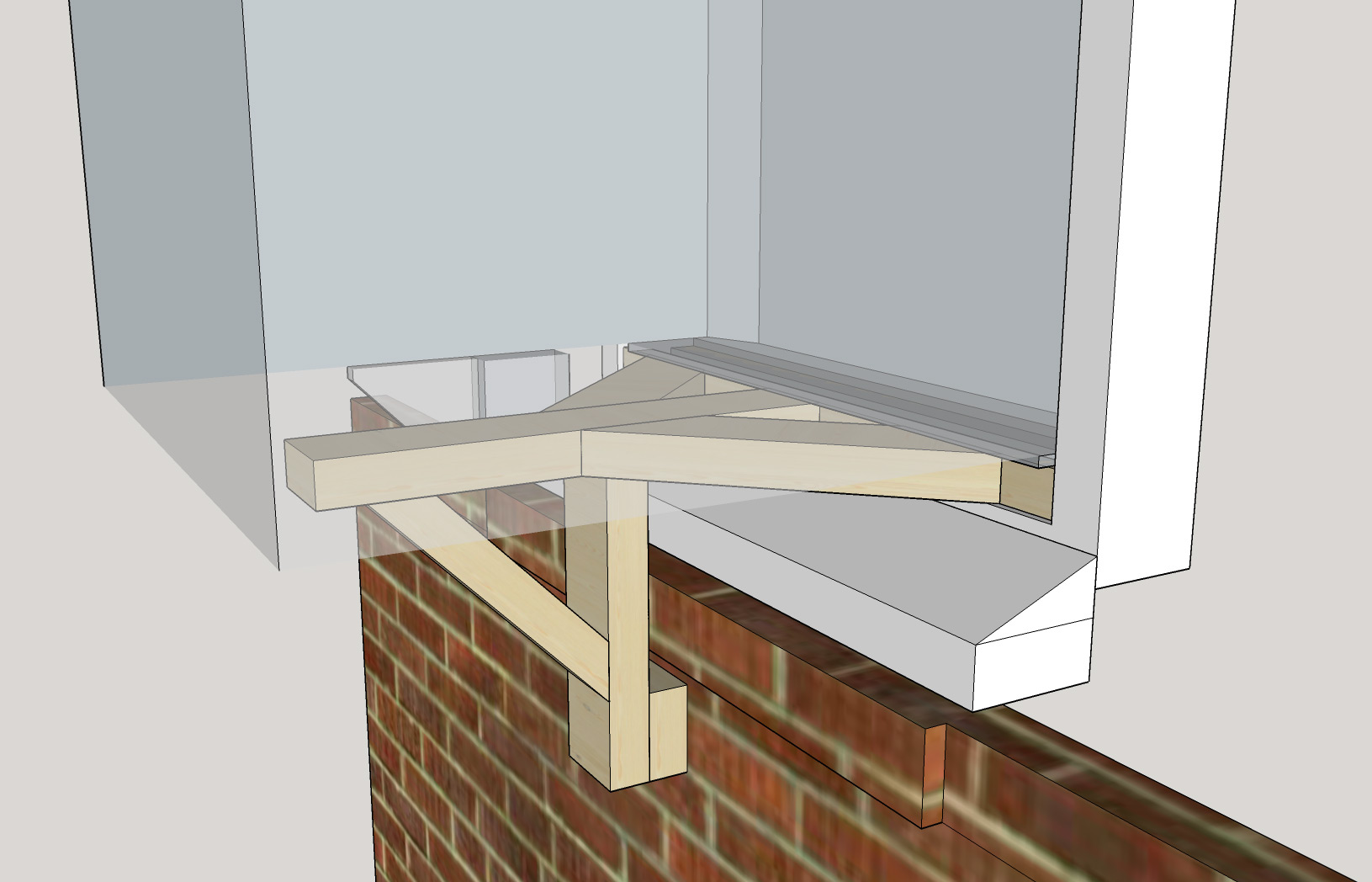
When I moved in here, the house still had the original single pane windows from the 40s installed. Not only did that merit attention, there was historically only a single air conditioner in the whole house — installed in the one window that had been replaced with a more traditional double-hung arrangement, to fit the A/C. And since it was responsible for the whole house, it is a big unit! Very early this year, we had all the windows replaced. That means they're "replacement" windows. Rather than being built into the house (i.e. "new construction" windows) they're designed to fit into the existing opening. Which means some of the structure of the window moves inward, to what used to be window opening. So, this one important window opening is now in a slightly different place, and the existing support structure won't hold up the existing A/C correctly. Given that it's such a big one, I wanted to be sure that we can hold it up well. So I came up with a design.

It starts with a 2x4 cut into a complex shape to fit around all the bumps and tabs in the window frame plus a bit at the bottom of the A/C which sticks down. Attached to that is another which sticks straight out, two to brace it, and then another which sticks down. This final one has both a triangle brace and an extra foot to reach around the brick window sill down to the main exterior wall of the house.

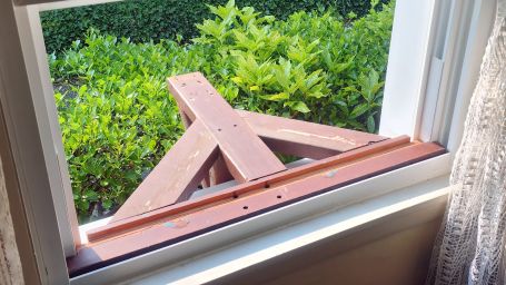
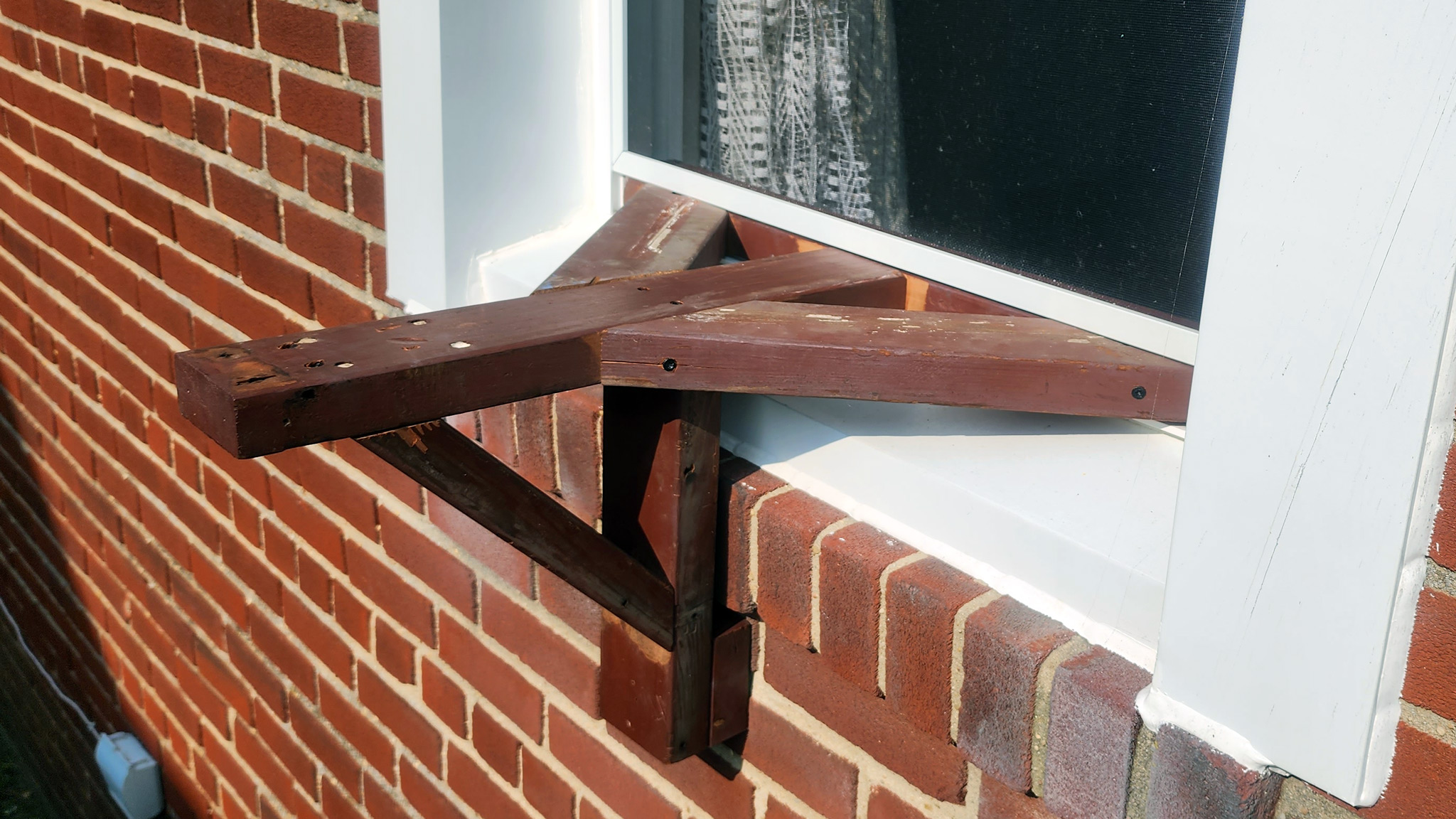
Here it is. It was built from reclaimed wood which used to be a bench. It's not the prettiest, but it will be underneath the air conditioner, so it doesn't need to be. It's full of extra holes, but that's OK. It's also wood from a product meant to be outside. I'm not sure what kind of wood, but it's reddish. I could believe cedar, either way it should stand up to the elements OK. Some of the building was done a bit freehand, but with the key sizes measured it came out extremely close to my original design. I can pretty well hang myself off it, so I'm sure it will hold the A/C up just fine.
2023-04-26 21:55 - Tech
A while back I set up a home server (and a remote backup server at my Mom's) with one primary goal: Proper KVM-over-IP, so that complete remote support and repair is possible. I ended up building around used SuperMicro server motherboards, which include IPMI (Intelligent Platform Management Interface) for remote management, including KVM (Keyboard/Video/Mouse) control and remote virtual USB media (boot from an ISO image located with/controlled by the IPMI client).
I ended up with oldish boards, to make them cheap. Oldish but "enterprise grade" is plenty for my needs! There's a catch though: newish IPMIView clients and oldish servers aren't 100% compatible. Reference some good community documentation at Reddit titled Fix X9DR Supermicro IPMI Colors Broken / Glitched (Archive) which even links to the official SuperMicro support page (Archive) — both of which instruct you to download some files from the IPMI device's built in web server, and replace part of the IPMIView client.
I did that, years ago at this point I want to say. More recently, I was trying to manage these servers, remotely. No matter what I tried, I would always get an error message "Session ID is Expired" when attaching the virtual media to boot from. (And I couldn't find this message documented anywhere online!) Generally to verify that if I reboot, I'll be able to do so from rescue media. But at least once, I really needed to do so. And I couldn't!
I tried lots of things over lots of time. Eventually, I could get it working in a completely blank virtual machine, with just IPMIView installed. Most of the time I did this, I instinctively patched the client files to fix the colors: I've known to do this, and done it as a matter of course, for years. At least once I must not have and after a while I figured out that's where things were working.
It's much more important that my lightly-used rescue environment works than that it looks pretty, so I've reverted the documented patching in all of my IPMIView clients, for now. (Though of course this kind of "for now" turns permanent pretty quickly.)